Summary
-
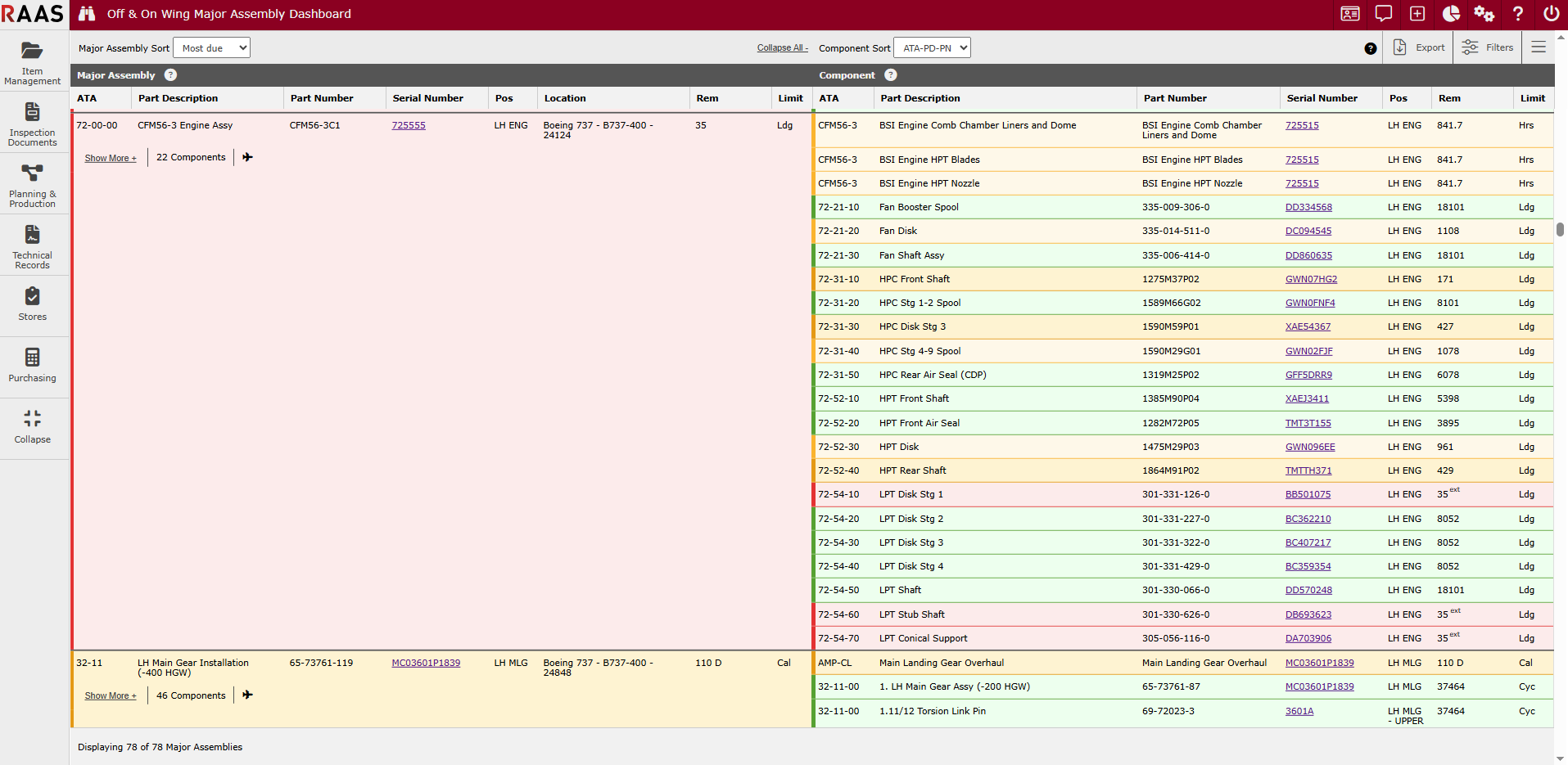
The Off & On Wing Major Assembly Dashboard indicates approaching due limits for engines or other major assemblies via configurable status colors.
-
The status of the major assembly as a whole is shown, in addition to the status of each constituent component.
-
Excel export is supported for offline analysis or sharing of data.
-
The dashboard is available as an option in the Dashboards section of RAAS.
Appearance
Data
-
Each major assembly is shown on its own card.
-
Major assembly cards have two sections:
-
Major assembly header information
-
Components of the major assembly, in list format
-
-
Each component shows the following data:
-
ATA
-
Part Description (PD)
-
Part Number (PN)
-
Serial Number (SN)
-
Position (Pos)
-
Remaining (Rem)
-
Limit (usually calendar, cycles, or hours)
-
Coloring
-
Four colors are used to indicate status, in order from most due to least due as follows:
-
Red
-
Orange
-
Yellow
-
Green
-
-
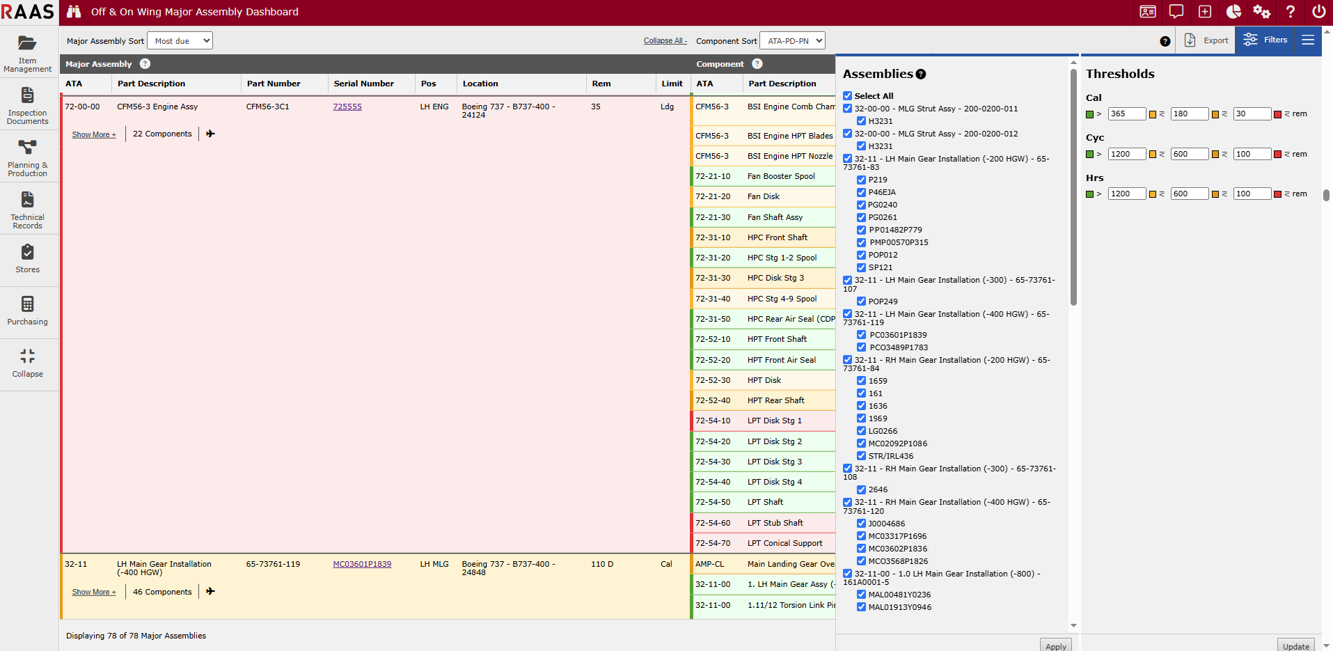
Color thresholds can be configured in the ☰ button menu.
-
Utilization is not used: each of calendar, cycles and hours limit thresholds are set independently.
-
Status coloring for a Major Assembly as a whole is determined by the soonest due, "worst" contained component.
Filtering
-
Filtering allows Major Assemblies to be hidden or shown in display.
-
Filters can be set in the "Filters" button menu.
-
Filter options are arranged in a two-level hierarchy:
-
Top-level options form groups of Major Assemblies having a common ATA, Part Description, and Part Number.
-
Bottom level options show Serial Numbers for individual engines, gears, or other Major Assemblies belonging to the top-level group.
-
Expand & Collapse
-
Clicking a "Show More" button shows all components for a single Major Assembly.
-
Clicking a "Show Less" button hides all except the most due component for each limit for a single Major Assembly.
-
Clicking the "Expand All" button shows all components for all Major Assemblies.
-
Clicking the "Collapse All" button hides all except the most due maintenance item for each limit for all Major Assemblies.
-
Collapsing shows the most due for each limit, in other words the "worst" single calendar, cycles, and hours limited components.
Grouping
-
Components are grouped by limit.
-
Component limit-defined groups are alphabetically ordered, such that calendar precedes cycles, which in turn precedes hours.
Order
-
Major Assemblies can be sorted in the following orders:
-
ATA-PD-PN order
-
Most due order
-
Status color, alphabetically ordered limit, and reverse remaining "time" are the keys comprising most due order
-
Location order
-
-
-
Components can be sorted in the following orders, within the limit-defined groups described above:
-
ATA-PD-PN order
-
Most due order
-
Icons and Indicators
-
Aircraft icons indicate on wing locations.
-
“ext” in superscript indicates a component in extension.
-
-
Extensions can be applied or removed in the Job Card editor.
-
“WIL” in superscript indicates a "whichever is later" component with multiple limits.
-
Utilization settings may affect WIL display.
-
Configuration
-
The "Major Assy (Has Tech Log)" checkbox must be selected in the Part Description editor of Item Management for a Major Assembly to become visible in the dashboard.
-
Sub-components of the major assembly must be set to "Requires Major Assembly Removal" in the Part Number editor of Item Management to be considered a valid cause for removal and become visible in the dashboard.
Miscellaneous
-
Limits set at the header level of a Major Assembly are also represented as components.
-
At least one component within the Major Assembly must be set to "Requires Major Assembly Removal" in the Part Number editor of Item Management for that Major Assembly to become visible in the dashboard.
-
Dead Major Assemblies are not available in the dashboard.
-
User account preferences are used to save the state of user interface controls.
-
All calendar limits are represented as days.
-
Limit labels respect settings defined in the Part Number editor, such that "Ldg" may be used in some cases and "Cyc" in others, for example.
-
Clickthrough links to the Serial Number editor are provided.
-
Excel exports are pivoted so that all limits for a component appear on one row.
-
Excel exports show all rows regardless of filter settings.
-
Excel exports include the Note field from the Serial Number editor.
Example